
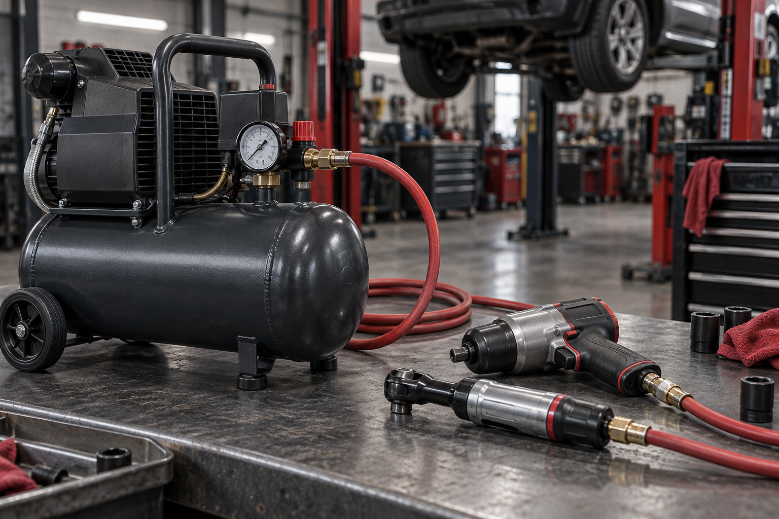
Choosing an air compressor for air tools starts with one question: how much air must reach the tool while it is working? The answer comes from the tool’s airflow requirement in CFM or SCFM at its specified operating pressure. Tank gallons, maximum PSI, and horsepower matter, but none of them replaces an adequate delivered airflow rating.
For a single tool used in short bursts, choose a compressor that meets the tool’s pressure requirement and can supply enough average airflow to recover between bursts. For continuous use or multiple tools, calculate the combined demand, account for both tool and compressor duty cycles, allow for pressure loss through the hose and air-treatment components, and add a justified reserve.
For specific tool examples, see our Air Tool CFM Chart. Abrasive blasting is a distinct sustained-airflow case covered in the Sandblasting Compressor Guide.
The Compressor Specs That Matter Most
| Specification | What it tells you | How to use it |
|---|---|---|
| CFM or SCFM at a stated PSI | How much air the compressor delivers at that pressure | Compare it with the tool requirement at the same operating pressure |
| Operating PSI | The pressure the tool needs while running | Confirm the pressure at the tool inlet under load, not just at the tank |
| Compressor duty cycle | How long the pump can run within a cycle without exceeding its design limit | Check the allowed run/rest pattern with the manufacturer and verify tank storage and recovery |
| Tank capacity | How much compressed air is stored between pressure limits | Use it to buffer short peaks and reduce rapid cycling, not as a substitute for compressor output |
| Power supply | What electrical circuit or engine the compressor needs | Confirm voltage, phase, amperage, plug, and ventilation before buying |
When comparing models, use delivered CFM or SCFM at the pressure you need. Pump displacement and peak horsepower are not direct substitutes for delivered airflow. A compressor rated at 10 SCFM at 40 PSI may deliver less at 90 PSI, so the 40 PSI number cannot be used to size a 90 PSI air tool.
CFM vs. SCFM: Compare Like With Like
CFM means cubic feet per minute. SCFM means standard cubic feet per minute, a flow value normalized to a stated set of reference conditions. SCFM makes compressor comparisons easier, but test conditions and labeling practices can vary. Read the footnotes on both the tool and compressor data sheets.
The most useful comparison is:
Tool airflow requirement at its rated pressure versus compressor delivered airflow at that same pressure.
If a tool requires 6 SCFM at 90 PSI, look for a compressor rating at 90 PSI. Do not compare that tool with a compressor’s maximum PSI, tank volume, or an airflow rating measured at a lower pressure.
Also determine what the tool’s airflow number represents. Some manuals list full-load consumption. Others list average consumption based on intermittent use. If the published value already includes an assumed use factor, do not reduce it a second time. When the label is unclear, use the manufacturer’s manual or ask the manufacturer for full-load airflow.
How to Calculate the Compressor Capacity You Need
Use this six-step worksheet before comparing products in the Air Compressors category.
1. List Each Tool’s Air Requirement
For every tool you plan to run, record:
- Required CFM or SCFM
- Rated operating PSI
- Whether the airflow is full-load or average consumption
- Quantity of that tool
- Percentage of time the tool will actually be running
- Which other tools can operate at the same time
Use the exact model’s manual whenever possible. A generic air-tool chart is only a rough screening tool because two tools of the same type can have very different air consumption.
2. Calculate Average Tool Demand
If you have full-load airflow values, estimate average demand with:
Average tool demand \= sum of (full-load SCFM x quantity x tool-use fraction)
Write the tool-use fraction as a decimal. A tool running 25% of the time has a use fraction of 0.25. This calculation is useful for intermittent work because it estimates how much air the compressor must replace over the work cycle.
Do not apply this factor to a published “average air consumption” value unless you confirm that the value represents full-load flow. Applying a second use factor can badly undersize the compressor.
3. Check the Compressor Duty Cycle and Recovery
Tool duty and compressor duty are different. Tool duty describes how much of the work period the tool draws air. Compressor duty cycle describes how long a particular pump may run within its rated cycle.
Read the compressor manufacturer’s allowed run and rest periods at the required pressure. Then check whether its delivered airflow, receiver storage and recovery time can support the tools’ actual pattern of use. A single duty-cycle percentage does not tell you how large a compressor to buy; the timing of each burst and the receiver pressure range also matter. If the compressor must supply a continuous load, use a model whose manufacturer explicitly rates it for that duty at the required output.
4. Check Simultaneous Peak Demand
Add the full-load airflow of only the tools that can realistically run at the same time:
Simultaneous peak demand \= sum of the SCFM for tools operating together
One technician switching between an impact wrench and an air ratchet usually does not need the sum of every tool in the drawer. Two technicians working at once may. A continuous-use grinder paired with an intermittently used impact wrench creates a different load from either tool alone.
If the overlap can continue for more than a short burst, size the compressor to the simultaneous demand. If the overlap is brief and the compressor has time to recover, a properly sized receiver tank can cover some of the shortfall.
5. Add a Planning Margin
After you establish the relevant airflow requirement, choose a reserve based on uncertain ratings, measured leaks, overlapping loads and future needs. CAGI does not prescribe one percentage for every system: steady demand may need a smaller margin than unpredictable intermittent demand. The second worked example uses 25% only as an illustration, not as a sizing rule.
Illustrative target with a 25% reserve \= required compressor output x 1.25
Use a larger margin only when the conditions justify it. Do not add separate large allowances for leaks, pressure loss, future growth, and general safety without checking for overlap. That can produce an oversized compressor that cycles poorly and costs more to operate.
6. Compare the Average and Peak Results
Use the larger capacity that matches the way you work:
- For sustained or frequently overlapping tools, screen the combined demand against delivered airflow, the manufacturer’s allowed duty cycle, receiver storage and recovery. Add only a justified planning margin.
- For intermittent tools with short peaks, screen average demand against pump-on output, then verify that the tank can cover each burst and recover before the next one.
- For an existing busy shop with irregular demand, measured airflow and pressure data are more reliable than estimates.
Worked Example 1: One Intermittent Air Tool
Assume an air tool uses 6 SCFM at 90 PSI at full load and runs for about 25% of a typical work period.
| Step | Calculation | Result |
|---|---|---|
| Average tool demand | 6 SCFM x 0.25 | 1.5 SCFM |
| Short peak while the trigger is held | Full-load tool demand | 6 SCFM at 90 PSI |
The compressor must replace the air consumed over the work cycle, while the receiver may help cover each short 6-SCFM burst. To choose a model, verify its delivered airflow at 90 PSI, the manufacturer’s permitted run and rest periods, receiver storage between usable pressures, and recovery before the next burst. For continuous tool use, the compressor must deliver at least the tool’s 6 SCFM at 90 PSI, plus any justified reserve, with a duty rating that supports uninterrupted operation.
This example shows why the work pattern matters. The same tool may be practical on a smaller system for short bursts but need a higher continuous output for sustained use.
Worked Example 2: Two Tools With Overlapping Use
Assume a grinder requires 8 SCFM at 90 PSI and runs continuously. An impact wrench requires 6 SCFM at 90 PSI and operates 20% of the time. The tools sometimes run together.
| Step | Calculation | Result |
|---|---|---|
| Average demand | 8 + (6 x 0.20) | 9.2 SCFM |
| Simultaneous peak | 8 + 6 | 14 SCFM |
| Illustrative average target with 25% reserve | 9.2 x 1.25 | 11.5 SCFM at 90 PSI |
| Illustrative sustained-overlap target with 25% reserve | 14 x 1.25 | 17.5 SCFM at 90 PSI |
The 11.5-SCFM figure is an average-demand screen, not a model recommendation. If the tools overlap only briefly, a receiver may buffer the 14-SCFM peak, provided pressure stays adequate and the compressor recovers before the next burst. If the overlap is sustained, delivered output must cover that combined load at 90 PSI for the full period. Check the manufacturer’s duty rating, receiver storage, recovery, and pressure at the tools before selecting a model. The 25% margin is only an example; choose a reserve justified by the real system.
Account for Operating PSI and Pressure Loss
Airflow and pressure must be sized together. The tool needs its rated pressure at the inlet while air is flowing. A tank gauge showing 120 PSI does not prove that a tool is receiving 90 PSI under load.
Use this relationship:
Minimum supply pressure \= required pressure at the tool + total system pressure loss
Pressure loss can occur across:
- Hose length and inside diameter
- Quick-connect couplers and fittings
- Regulators, filters, and dryers
- Valves, manifolds, and piping
- Leaks and damaged hose
Loss rises with airflow and distance, and it rises quickly when a hose or fitting is too restrictive. Use the hose or component manufacturer’s pressure-drop chart at your planned flow. Then check the result with a gauge at the tool inlet while the tool is operating.
Never solve pressure loss by exceeding the tool’s maximum inlet pressure or the rating of any hose, fitting, filter, regulator, or tank. Reduce restrictions first. A correctly sized regulator controls outlet pressure, but it cannot create airflow that the compressor and distribution system do not provide.
Choose the Right Air Hose Size
Hose size should follow the tool’s airflow, the run length, and the fitting size. A hose diameter that works for one tool and run length may be too restrictive for another. Use the hose and fitting manufacturer’s pressure-drop data at your required flow rather than a universal diameter rule.
When pressure loss is too high:
- Increase hose inside diameter.
- Shorten the run where practical.
- Replace restrictive quick connects with higher-flow fittings.
- Remove unnecessary elbows and adapters.
- Check filters and regulators for adequate flow capacity.
- Repair leaks.
Browse Air Hoses & Reels after you know the target flow and length. Match the hose and every fitting to both the compressor’s maximum pressure and the tool’s airflow requirement.
What Tank Capacity Does for Pneumatic Tools
A receiver tank stores compressed air. It helps with short bursts, smooths pressure fluctuations, reduces rapid motor cycling, and gives an intermittent-use compressor time to recover. It does not increase the pump’s continuous CFM.
Tank needs depend on the size and duration of each demand spike, the compressor’s output while the tool is running, the pressure at which the tool stops performing properly, and the time available for recovery.
For a rough, idealized estimate of usable standard free air between two tank pressures:
Usable free air in cubic feet \= tank volume in cubic feet x (high pressure – low pressure) / 14.7
There are about 7.48 gallons in one cubic foot. If tool demand exceeds compressor output during a short event:
Approximate buffer time in minutes \= usable free air / (tool demand – compressor output)
Example: a 30-gallon tank is about 4.01 cubic feet. If usable pressure can fall from 150 PSIG to 110 PSIG, the idealized stored free air across that range is:
4.01 x (150 – 110) / 14.7 \= about 10.9 standard cubic feet
If the tool uses 12 SCFM and the compressor supplies an average of 8 SCFM across that pressure interval, the deficit is 4 SCFM. The idealized buffer is about 10.9 / 4, or 2.7 minutes. Real usable time will be lower because of temperature changes, controls, pressure loss, and the need to maintain pressure at the tool. Treat this as a planning estimate, not a guarantee.
If demand is continuous, the tank will eventually empty to its lower usable pressure whenever tool consumption exceeds compressor output. Choose more delivered CFM for sustained work.
Match the Compressor Format to the Work
Once the airflow and pressure numbers are settled, compare the format and ownership details.
Portable or Stationary
Portable compressors suit tire service, jobsite work, fastening, and short-burst repairs when their delivered airflow meets the tool requirement. Stationary models usually offer more output, storage, and electrical demand, making them a better fit for fixed garages and multi-bay shops.
Electric or Engine-Driven
Electric compressors work well indoors when the shop has the correct circuit. Confirm voltage, phase, amperage, and startup requirements. Engine-driven models provide mobility where power is unavailable, but they require ventilation and must not be operated in enclosed spaces.
Reciprocating or Rotary Screw
Reciprocating compressors are common for intermittent garage work. Their allowable duty cycle varies by model. Rotary screw compressors are commonly selected for steady, high-duty demand. The right choice depends on the measured load profile, not the technology name alone.
Oil-Lubricated or Oil-Free
Oil-lubricated pumps often suit longer shop use but require oil service. Oil-free pumps reduce that maintenance and can be useful where oil carryover is a concern. Noise, service access, replacement parts, and required air quality should all be reviewed before purchase.
Do Not Overlook Air Treatment and Accessories
Water, dirt, oil carryover, and pressure instability can reduce tool performance and service life. Browse air compressors, then choose treatment components with flow ratings that meet or exceed the system demand. A component can become a bottleneck even when its pressure rating looks adequate.
Check the air tool manual before adding a lubricator. Some pneumatic tools require regular oiling, while other processes require oil-free air. Paint and finishing work may need more extensive moisture and contamination control than general mechanical tools.
The Air Tools category can help you identify the exact models you plan to use. Verify each tool’s current specification sheet rather than relying on a broad CFM chart.
Air Compressor Buying Checklist
Before you buy, confirm all of the following:
- Compressor delivered CFM or SCFM is rated at the pressure your tools require.
- Tool airflow numbers are clearly identified as full-load or average consumption.
- Average demand, the compressor’s stated duty cycle, receiver storage and recovery have been checked together.
- Simultaneous tools have been added only when they can actually overlap.
- A reasonable planning margin has been added once, without double-counting every allowance.
- Pressure loss has been checked across the hose, fittings, regulators, filters, and dryers.
- Hose inside diameter and length are appropriate for the required flow.
- The tank can support short bursts and recover between them.
- Sustained tool demand does not depend on the tank to make up a permanent CFM shortfall.
- The electrical supply, ventilation, space, noise, maintenance, and mobility needs fit the shop.
- Every component is rated for the system’s maximum pressure.
After completing the worksheet, compare your result with the models currently available in National Tool Warehouse’s Air Compressors category. Product availability changes, so verify the specifications and stock of any model you shortlist. Select by delivered airflow at your required PSI, duty-cycle rating, tank configuration, and power requirements rather than by tank gallons alone.
Frequently Asked Questions
What size air compressor do I need for air tools?
Choose a compressor by the tool’s CFM or SCFM requirement at its operating PSI. For continuous use or multiple tools, calculate average and simultaneous demand, check the compressor’s duty rating and recovery with its manufacturer, allow for pressure loss, and add a reasonable reserve. Tank size should be selected after the airflow requirement is known.
Is a higher-PSI compressor enough for a high-CFM tool?
No. PSI measures pressure, while CFM or SCFM measures airflow. A compressor can reach the required pressure and still fail to supply enough air volume to keep the tool running. Compare delivered airflow at the required operating pressure.
What if my air tool lists CFM but not SCFM?
Check the manual for the test pressure, reference conditions, and whether the value is full-load or average consumption. If those details are missing, ask the manufacturer. Do not assume that two unlabeled CFM values were measured the same way.
Do tank gallons determine whether a compressor can run a tool?
No. Tank gallons determine stored-air capacity. A larger tank can extend a short burst and reduce cycling, but the pump’s delivered airflow determines whether the compressor can keep up over time.
Can one compressor run two air tools at once?
Yes, if it can deliver the combined airflow at the highest required operating pressure after realistic losses and reserve are included. If the tools overlap only briefly, the receiver may buffer the peak. Sustained overlap requires enough compressor output.
How much extra CFM should I allow?
There is no universal extra-CFM percentage. Choose a reserve for uncertainty, leaks, possible simultaneous use and future growth. The 25% used in one worked example only illustrates the calculation. Avoid stacking several broad allowances that cover the same risk.
What air hose size should I use for pneumatic tools?
Choose hose inside diameter from the required airflow, run length, and the manufacturer’s pressure-drop data. Do not rely on one diameter for every tool. Confirm the pressure drop for the chosen hose and fittings at the required flow, then check delivered pressure at the tool while it is running.